Finished? Never!

Of course, this project will never be finished, but it has come to a kind of “beta” version anyway. I can happily fire it up and take it for a spin, everything seems to work, and it is a lot of fun.

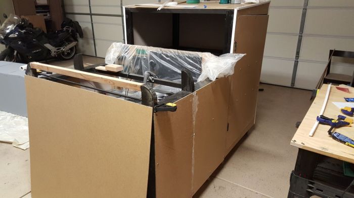
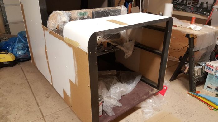
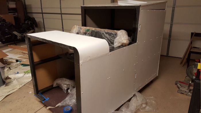
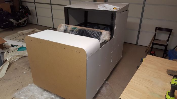
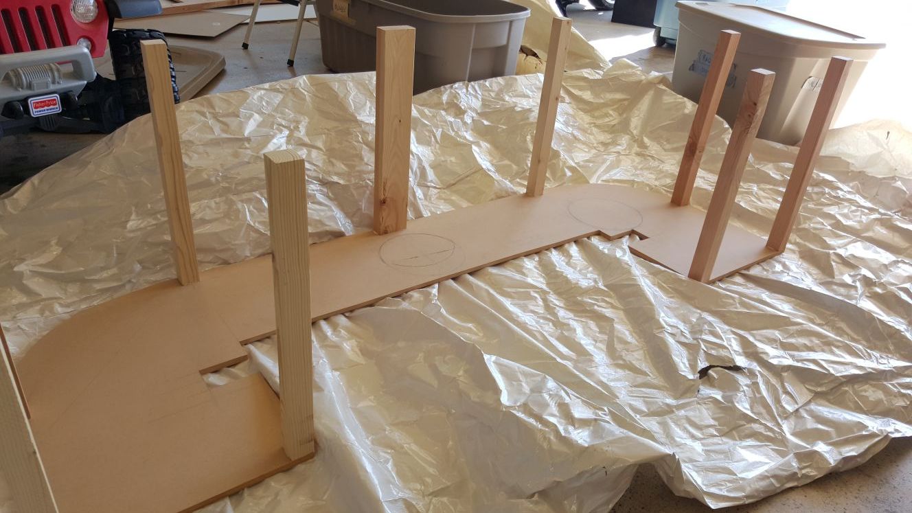
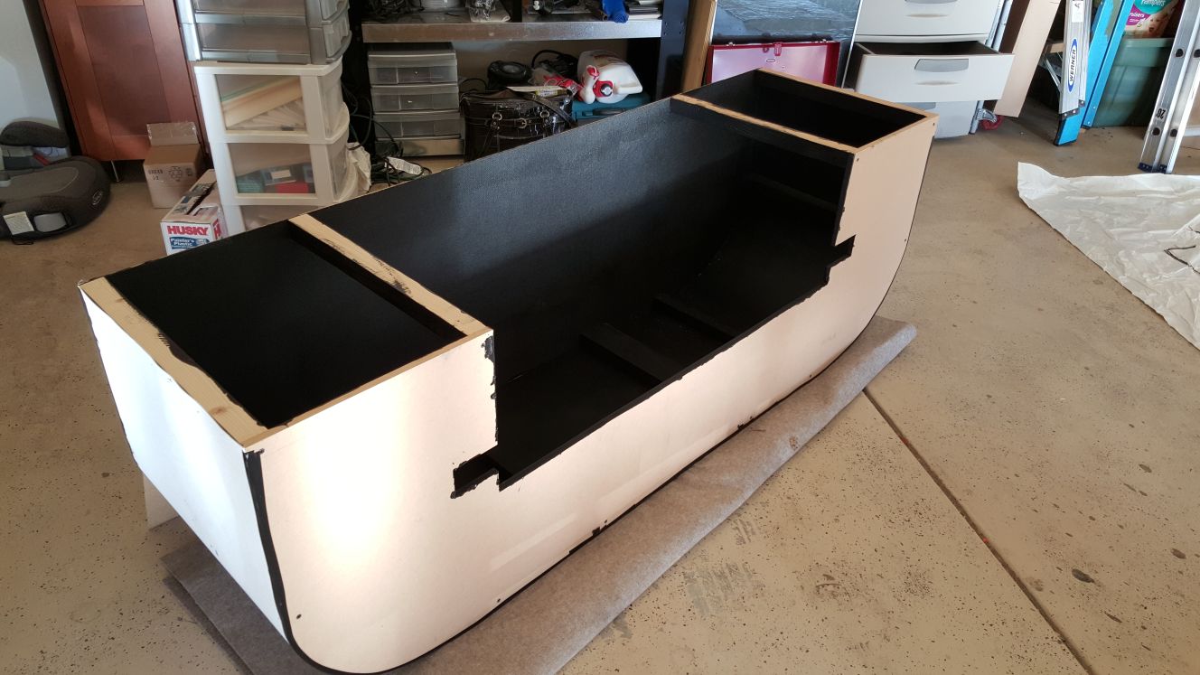
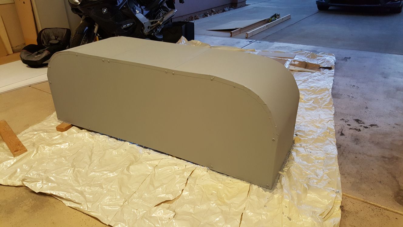
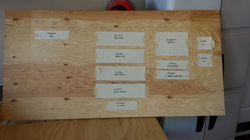
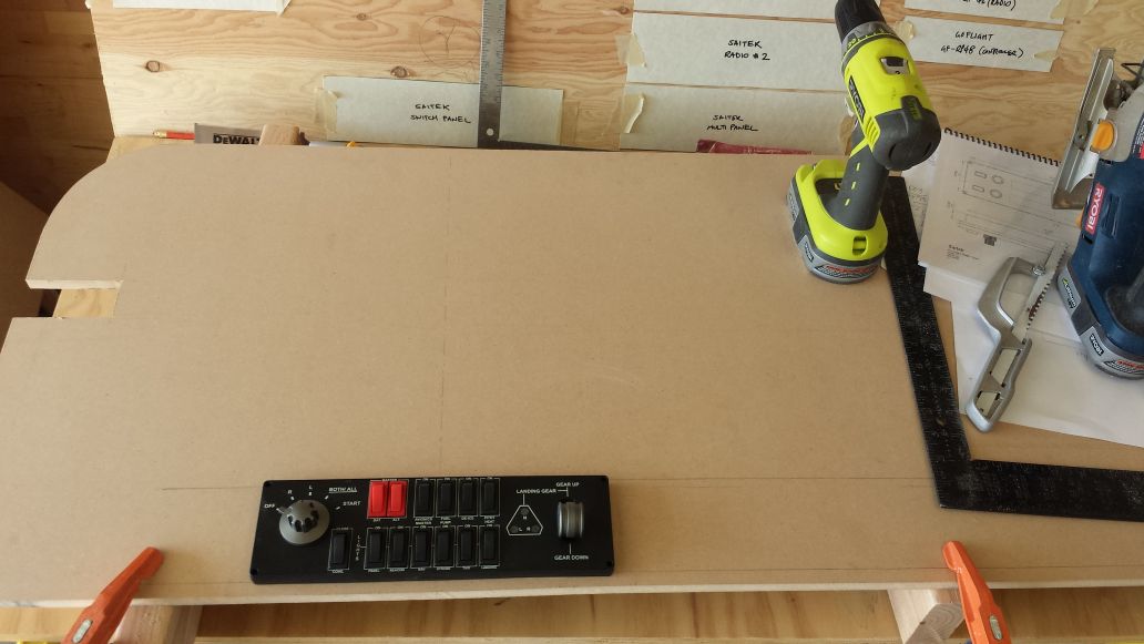
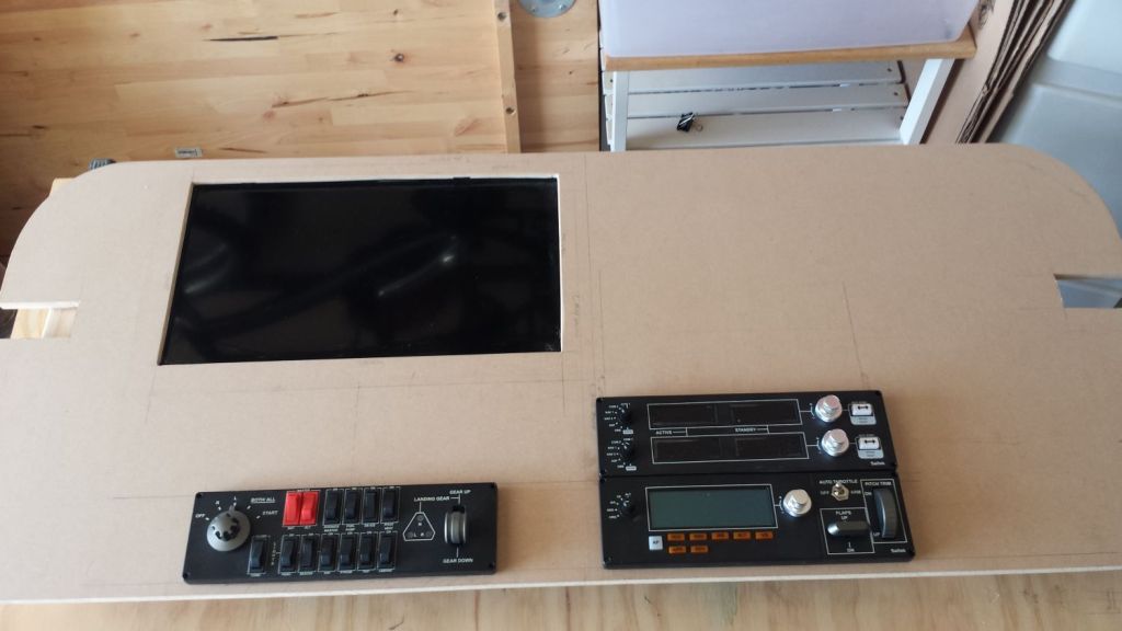
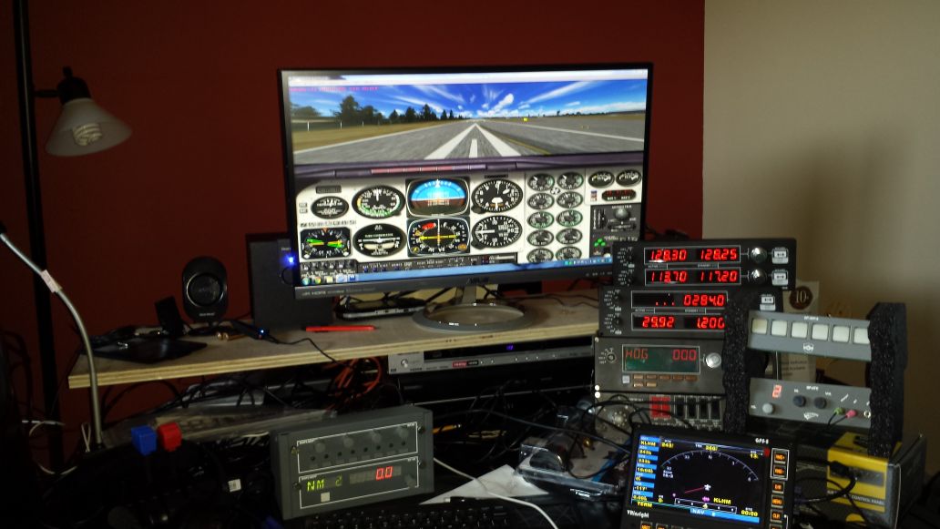
Here’s a few photos of what it looks like at this stage:

Of course, this means I can now identify all the things I wish I had done differently. But those can go on to the “to do” list for the next iteration. Meanwhile, here are some thoughts on what I have discovered so far.

Too much stuff?

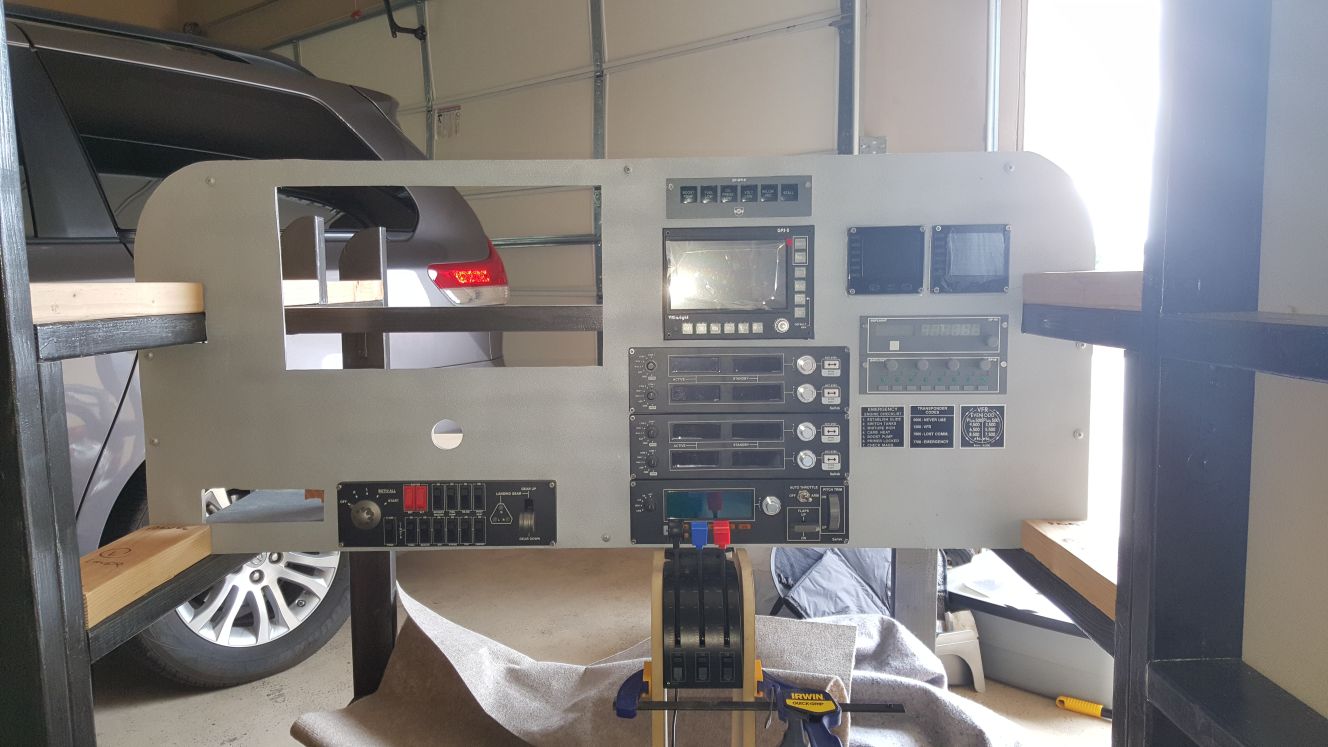
The panel has a lot of stuff,  some of it isn’t totally useful, and some of it is redundant, but I’d rather have too much than not enough. But it does mean there’s room to add more panel functionality later on. However, right now, most of what I need is concentrated in about 3/4 of the gadgets.

In particular, two Saitek radios is overkill — I was thinking I would use one for COM1 and COM2 and the other for NAV1 plus something else. However, so far I have only used one radio: line 1 is COM1 and line 2 is an altimeter setting and transponder (thanks to FPUIC). The second radio ended up under the yoke for now — more on that below.

Button overload

From the outset, I had a goal of being able to fly around without touching a keyboard, except maybe to load and save the flight. Not only for all aircraft controls, but also things like pause, zoom, sim rate, etc.

To the end, I overloaded the cockpit with buttons, and left the programming to the end. That left me with a lot of button mapping to do. The best gadget for this was the 24-key X-Keys panel, which I mounted on the throttle quadrant. Right now it is about 50% utilized.

The yoke buttons are almost all unused so far, as are the rockers on the Saitek throttle quadrant (although I have plans for those). I also have a GF-48 with buttons yet to be programmed.

However, the more I fly, the more I identify things that would be handy to have assigned to a physical button (like “summon fuel truck”), so over time, utilization will increase – the only problem will be remembering them

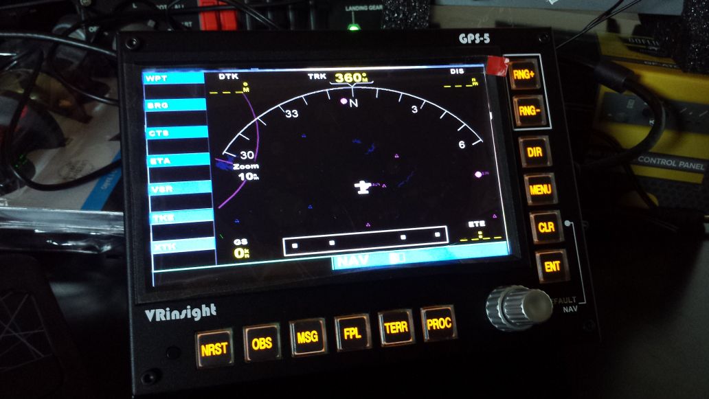
VRInsight GPS-5 is great

My most favorite gadget. This thing works like a charm and is great for the type of flying I enjoy. Plus, it is really a good opportunity to learn the ins and outs of all its features, which should help if ever I come across a real Garmin GPS 500.

It was pretty easy to set up, and despite instructions to the contrary, also seems to work in full-screen mode too (not just windowed mode).

Lighting not so great

The inside of the cockpit is dark! This seems pretty obvious in hindsight. It was actually obvious as I built it, which is why I added a marine dome light in the roof (which features both red and white LEDs).

However, it turns out I need the dome light on all the time in order to see the various button and dial labels on things like the Saitek panels. Some actual panel lighting would be much better – maybe I can find a way to put a strip of LEDs along the header, and then use the dome light for looking at charts, etc.

The LED strip lighting that illuminates the footwells came out really good though, and adds a nice touch of ambiance.
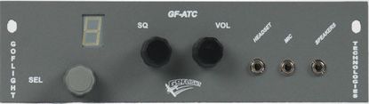
GF-ATC

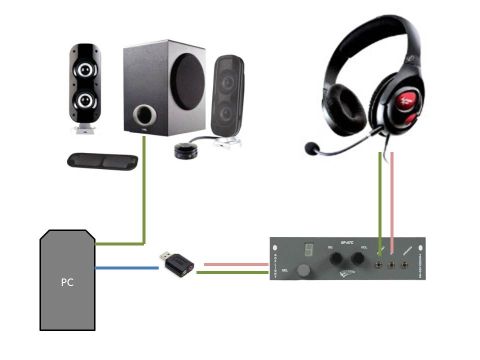
Another great gadget – I have the engine and environment sound piped through a 2.1 speaker system (and it can be pretty loud), but the comms go through a headset, which I plug in to the GF-ATC panel.

I can open and close the on-screen ATC window, as well as select any of the options, using just the GF-ATC and no keyboard, which is great. And although sometimes it feels like cheating to press “1” to set COM1 to the correct frequency, sometimes it is essential, since the Saitek radio only support two decimal places, whereas many frequencies have three.

But apart from that, I choose either “cheat mode”, and use the GF-ATC to select the numbered option in the ATC window, or I dial it in myself.

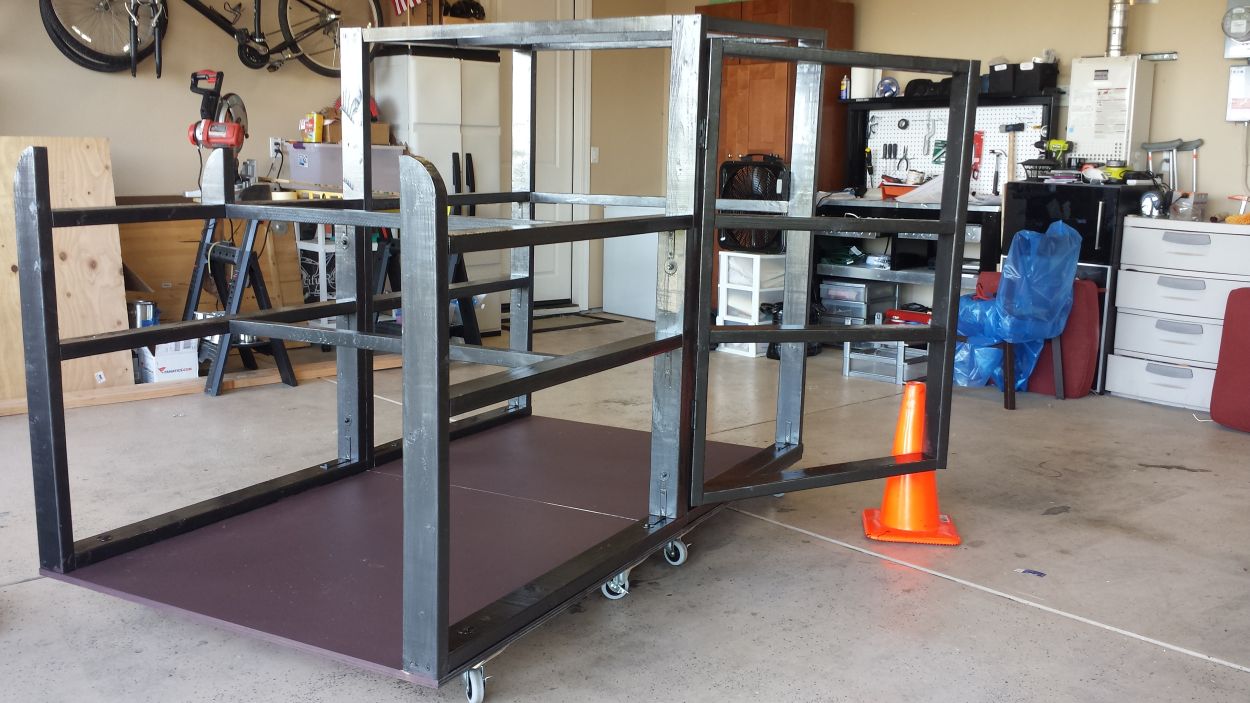
Construction details

There were a few construction details I left to the end, but didn’t get around to finishing. First, the door needs a latch to keep it closed (from the inside and from the outside). Second, the foot-wells need to be finished; right now you can peer down at your feet and see straight through to the “engine compartment” (i.e. the PC, subwoofer and a USB hub), which is mostly a problem on the passenger side.

Point of view

I knew this would be weird from the beginning, and after a few flights, it became very obvious.

The problem is, the cockpit is laid out with the pilot on the left side of center (like a real cockpit), but the view is drawn as if the pilot is in the middle of the view. This makes things like following a taxi line, or lining up with the runway centerline, kind of more difficult than it should be.

Now, I wanted the physical cockpit layout to be offset for sure, and figured I’d find a way to mess with the view later on. It turns out you can move the view point left and right, so I have been playing with shifting it so that the taxiway line, when it is under the nosewheel, lines up with the center of the yoke.

Frame rates

This will be another post all of its own one day. For now, suffice it to say I am still tinkering. Currently I get about 30 to 40 FPS over “open country” and about 20 over a crowded city. This is with the graphics options pretty much cranked all the way up, auto scenery on “dense”, about 20% air traffic, and almost no ground traffic.

More details to follow…

Add-ons

So far I have not tinkered with add-ons, except some scenery from OrbX: I am using their North America Northern California scenery, and one add-on airport (Lake Tahoe). Absolutely loving it so far, and can’t wait to add more airports. Oh, and I have their “FTX Trees” installed too.


Cockpit Exterior

The past few weeks have been spent finishing the exterior of this CS-1 Stallion. It is in this stage where I find out how straight all my framing is (or isn’t) – in theory all the side panels should be nice clean rectangles that attach and align perfectly.

The reality was a little different. In the end, the best method I found to finish the exterior was to use large pieces of cardboard as fake side panels, tape them roughly in place, and mark out the exact edges. Then, I used these as templates for cutting the fiberboard.

This gave me fiberboard pieces that all fit together pretty well, even though some were slightly skewed in shape.

20151104_225720
The exterior panels being put into place. To tidy up some of the edges, I glued some strips of L-shaped plastic edging

Cowling

The panel for the “cowling” gave me a few problems. Looking at the plans, it looks clear that the intent is to have a curved panel over the “engine compartment”, and the four curved 2X4 ends provide the framing for that. However, fiberboard is just not flexible enough to bend that much. I guess I didn’t really think about how this was supposed to work until I actually tried it.

I ended up resorting to the trusty Polywall plastic sheeting (the same stuff I used for the instrument panel overlay ). Although it has a little texture, whereas the fiberboard is totally smooth, I figured the paint would even it out a little, and I could live with the result.

20151109_230054
Creating the cowling from PolyWall plastic. Here it is taped down while I add nails to secure it.

Since the Polywall is pretty flimsy, I had to add two more horizontal lateral beams of 2X2 to support it. Luckily I had plenty left over. The Polywall section was then nailed at each end and all along these sections of 2X2. In end, it looked pretty good. And as long as I don’t go placing the week’s grocery bags on top of it or something, it is strong enough for its purpose.

20151111_220514

Nose

The panel that covers the front (which I’ve been calling the “nose”) was last. It was easy enough to cut this to shape. However, instead of screwing it to the frame like all the other panels, I glued some sections of 2X2 to the inside face so that it made a very snug fit with the frame: with just those in place, the panel would hold itself in position just by friction, while still being easy to pull off.

20151111_232228
The “nose” panel cut to shape and put into place. It is held in place with some tight-fitting framing and magnetic latches, to make it easy to remove

To make it a little more robust, I added some magnetic closet door latches to the frame and the nose panel to hold it in place a little better, and finally added a couple of handles to facilitate removing and replacing it.

The end result means I can just pull this panel off, set it aside, and have full access to the interior section where all the computer hardware will sit. Very useful.

Paint

I painted the entire exterior with a high gloss white latex paint. I plan to add more color to that later, but for now this is it. It’s time to start working on some of the interior features. Stay tuned!

Instrument panel build, part #2

When I last updated this blog with work on the instrument panel, it was about three months ago. Since then I simply continued the path I was on, cutting holes for each instrument and making them all fit nicely.

There was a lot of hole cutting to do, and back then I did not have the “Rotozip” tool that I have now, so I did it the hard way by drilling out each corner and using a jigsaw to cut from corner to corner.

Once all the holes were cut, and I made sure each piece of equipment would fit, I covered the entire thing with a sheet of Polywall (1/16th inch thick plastic). This stuff has a very subtle texture to it (one side more than the other) and, when painted metallic grey / silver, looks almost like aluminum. Almost! It’s certainly a lot easier to work with.

Panel when covered with Polywall and painted metallic grey to look a bit like aluminum

Of course I then had to cut all the holes again, but at least this time I could use a sharp box cutter, and the edges would come out nice and straight with nice clean corners. Once those were cut I could insert the equipment, and the result is shown in the picture below:

All the equipment added to the panel, and placed into position in the cockpit

Of course, the monitor for the main flight instruments is missing here, as is the yoke. I will cover those later. You might also notice a small hole in the lower left: that is where a GoFlight ATC panel will fit: I just hadn’t inserted it when I took the photo. You can also see the early beginnings of a center console, which will hold the throttle quadrant and other stuff. Again, more on that later.

The picture below shows the panel when viewed from behind. All the cables are taped up to keep them out of the way; eventually they will all feed through a cable duct into space where the PC will sit. Also visible in this picture is the horizontal “deck” that I can attach stuff to as needed, and the small shelf that the yoke will sit on. And you can see the whole through which the yoke shaft will protrude.

Panel as viewed from behind

The final picture shows a wider angle shot of progress so far (at least when the photo was taken: I’m a bit behind posting these updates!). The cockpit has a roof, two walls, and a door, and the panel is just resting in place in this picture (not yet secured). The dining chair is just a temporary fixture!

panel-16

Monitor hood progress

The plans for the CS-1 Stallion cover two options for the primary display: a large hood to hold up to three widescreen monitors, or an open front for viewing a projector screen. I chose the first option for my sim, and recently started on building the hood.

There were a few things about the design that I had to change:

First, the plans say to use a sheet of MDF for the top and for the bottom. However, this was going to be very heavy using the 1/2″ MDF I have available, so I decided to use fiberboard for the top. The whole thing is still very stable but it is easier to lift (although still very cumbersome and take two people most of the time).

All the main pieces for the hood cut out and ready for assembly

Second, the position and number of vertical supports. Due to the large bases on the monitors I chose, a center vertical support made from a length of 2×4 wasn’t going to work — the center monitor would be pushed too far forward. So I replaced that with two verticals instead. When securing the top and bottom panels to the uprights, I used the “screw plus finishing washer” combination, which (when painted) make a passing resemblance to an aircraft rivet.

Bottom and uprights. Note this was BEFORE I realized my center monitor wasn't going to fit!
Bottom and uprights. Note this was BEFORE I realized my center monitor wasn’t going to fit!

For the outer surround, I used Polywall; a plastic sheeting used for waterproofing behind drywall. I used the same thing for the instrument panel overlay so had plenty to spare. This stuff is thin, so is very flexible, easy to cut, and makes a nice curve shape (assuming the curves in the top and bottom panels were cut nicely to begin with). It was easy enough fit this to the hood and then secure it with small finishing nails along the top and bottom edges and where it meets the vertical supports.

Assembled and with interior painted

Once the whole thing was put together, I found that (since my carpentry skills are far from perfect), there were still some gaps here and there where the edges meet. I decided to run a length of some super-strong industrial tape (kind of like duct tape but way stronger) along all the join edges. This created a complete seal and stopped any light from leaking around the corners. It’s not perfect (fitting straight tape around a curved edge doesn’t work very well) but meets my “good enough” criteria.

Finished hood showing the bottom panel.

The inside was painted flat black (acrylic) and the outside I painted a basic flat grey. Adding the paint made a huge difference — this thing is made up from MDF, fiberboard, plastic, and tape, and looked pretty ugly in its unpainted form.

It might be fun to paint fake windows on it one day, but right now I’m kind of “done” with it and so it will stay lying on the garage floor until it’s ready to be mounted.

Finished hood showing the top panel

I should point out that getting the hood to fit perfectly in the space designed for it was a hassle. It was my mistake to create the space for it on the main cabinet before it was totally finished: the finished hood was a fraction larger than I anticipated and I had to do some last minute surgery to get it to fit.

Finally, if you are building one of these for yourself, bear in mind that it is VERY important to check that your monitors will fit as desired. I was VERY lucky in that the three 27″ monitors I had already bought did in fact fit … it’s not so much about total overall width or height of the hood, but more about whether your monitor stands let you position them in the way you want. Don’t pick monitors with very large stands, and make sure the ones you do pick can be returned if they won’t fit.

Instrument panel build, part #1

Now that I have all (well, almost all) of the components I need for the instrument panel for my CS-1 Stallion, I have started to build it. It has taken quite a while to figure out exactly where all the components should go, and I’m also not that great at building stuff, so I’ve been taking it slow.

I chose 1/2″ MDF for the panel because it seemed easiest to work with, and has a smooth finish, which I am hoping will be easy to paint when done. The plan is to paint it part black and part aluminum/grey, and add some fake rivets here and there to make it look more realistic.

Right now though, the task at hand is to lay out the panel. I’ve been sticking cardboard cutouts on to a piece of scrap plywood as a dummy panel to try out various ideas. At first, I was thinking of stacking all the Saitek panels in one column in the middle, and putting the rest on the co-pilot side, as shown below:

panel-1
Mock-up of original panel layout, with all Saitek panels in the center column and GPS to the far right

However, after making a cardboard cutout of that, and sitting in front of it for a few minutes pretending to push the buttons, I decided to move things around. Now, the Saitek switch panel is under the yoke, and the GPS is top center. The yoke is a little higher than the original CS-1 Stallion plans, but it’s at a comfortable height for me. The GoFlight panels, and the two Saitek Instrument Panels will be on the co-pilot side.

Revised idea, with Switch Panel under the yoke, and the GPS top center

Of course the hard thing with this layout is the yoke shaft needs to protrude through the panel, in between the switch panel at the bottom, and the monitor at the top. The Saitek yoke does not disassemble that easily — it’s possible to remove the yoke and shaft from the base, but it’s kind of delicate, and not really suitable for rough handling on a workbench while I build around it. So, I think I will cut a slot down from the monitor cutout, save the piece of MDF that is removed, slide the yoke shaft down, fix it in place, and then put the piece of MDF back. I’m hoping that in the end, it will look just fine.

(Speaking of Saitek yokes, I found a site that describes a quick and easy way to improve the handling of the pitch and roll movements using just a screwdriver and a rubber band: http://www.sehlah.com/yoke.pdf. A few minutes well spent.).

With the new plan in mind, I started some of the cutouts. As you can see below, I’ve got the switch panel and multi-panel in place, and a cutout for the monitor. Still a lot of work to do, but at least this is a start.

First component in place!
20150630_133858
A little more work done

Saitek Instrument Panels and Prepar3D

I tried out a Saitek Flight Instrument Panel (FIP) with Prepar3D 2.5 yesterday, and despite various claims that it should just work out of the box, it did not. It wasn’t hard to fix the problems, so I thought I’d post here for reference.

First, I downloaded the drivers from saitek.com, and installed those before plugging the panel in to any USB port. No problems there.

Then, plugged in the FIP; it came to life and showed a few ads for other Saitkek products. So far so good.

According to the documentation, all I had to do then was start up P3D, perhaps click “OK” to accept the driver, and the FIP would start showing some default instrument. However, nothing happened.

(1) Looking at P3D’s C:\Users\USERNAME\AppData\Roaming\Lockheed Martin\Prepar3D v2\exe.xml file, I can see the installation of the FIP driver added a section to launch SaiFlightSimX.exe on startup of the simulator:

<Launch.Addon>
  <Name>Saitek Panel(s) Plugin for FSX</Name>
  <Disabled>False</Disabled>
  <Path>C:\Program Files (x86)\Saitek\DirectOutput\SaiFlightSimX.exe</Path>
  <CommandLine>-run</CommandLine>
</Launch.Addon>

(2) I made sure that file existed, and it did. So, I tried to run SaiFlightSimX.exe manually by double-clicking it — it failed with some “side-by-side configuration” error. A ha! Luckily for us, the manifest file for SaiFlightSimX.exe is right there in the same folder, so I could see what dependencies it had; just open SaiFlightSimX.exe.manifest in any old text editor:

<dependentAssembly>
  <assemblyIdentity type='win32' name='Microsoft.FlightSimulator.SimConnect' version='10.0.61259.0' processorArchitecture='x86' publicKeyToken='67c7c14424d61b5b' />
</dependentAssembly>

Seems that SaiFlightSimX.exe depends on SimConnect version 10.0.61259.0. Looking at the “Add/Remove Programs” control panel showed that I had 10.0.60905.0 installed. So, I needed to find 10.0.61259.0 from somewhere…

(3) Luckily for us, Lockheed Martin includes all the flavors of SimConnect with P3D; they are all located under C:\Program Files (x86)\Lockheed Martin\Prepar3D v2\redist\Interface\<FSXVERSION>\retail\lib — the SimConnect.msi files are the installers I needed. After some web searches, I found that version 10.0.61259.0 corresponds to “FSX-SP2-XPACK”.

I installed SimConnect.msi using that package, and then checked the “Add/Remove Programs” control panel again to make sure I now have both 10.0.60905.0 and 10.0.61259.0 installed. Then, I tried to run SaiFlightSimX.exe manually again — this time there was no error, although nothing happened. But that’s OK, at least the .exe file starts without errors…

(4) Finally, I went back to P3D — bingo! This time, the FIP came to life showing an altimeter, and after that worked just perfectly.

Hopefully these instructions might be useful to someone else, although I’m sure the same or similar instructions are posted elsewhere.

Audio for the cockpit

Not many threads on the forums discussion audio too much, probably because it’s fairly simple. But I wanted to make a few notes about how I set things up.

I wanted something respectably loud for the main simulator sounds (engine, mainly), and I also wanted to use a headset for the ATC stuff. So, sounds for environment should be piped to some speakers mounted in the cockpit, and ATC sound to a headset.

I used the audio connections on the motherboard for the main speakers. An average (38W) 2.1 setup seems adequate right now (its hooked up in my office while I stage things in preparation for moving into the cockpit). Sound quality is decent and I think this should fill the cockpit with enough noise. Like many other such speaker sets, this has a “remote” with a volume control, which I can mount under the panel somewhere, for convenience.

Cyber Acoustics CA-3810 2.1 Speaker System

For the headset, I bought a simple under-$10 USB sound adapter. My original plan was to mount this adapter somewhere in the cockpit, and plug my headset into it. However, since the GF-ATC module from GoFlight just went on sale, I bought one of those, so I ran 3.5mm cables from the USB adapter to the GoFlight module instead.

Syba SD-CM-UAUD USB Stereo Audio Adapter

I picked a headset mostly by random at Fry’s. Time will tell how well it works. I wanted something that wasn’t going to silence the background noise too much (many of them are designed to do exactly that, for good reasons: my requirement is pretty odd), so these seemed like a good bet.

Creative Fatal1ty gaming headset

Then it was trivial to change the settings in Prepar3D to send the main sounds to the speakers, and voice to the headset.

The GoFlight ATC module works perfectly. Just turn the dial to select one of the 0-9 options in the ATC window, and push the dial to select. You can also dial it to “-“, which is the same at the apostrophe key, to open and close the ATC window. One less reason to pull out the keyboard during flight, and it adds a nice little touch of extra realism to the experience.

Audio schematic
Audio schematic

Like everything else so far, this is all set up in the “staging area” (i.e. the table in my home office), waiting to be transferred into the cockpit when it’s ready.

Notes on the VRInsight GPS-5

My GPS-5 from VRInsight arrived a few days ago, and I was keen to set it up and see how it looked. I just got it working for the first time today, and thought I’d share some notes on the experience.

I ordered it on June 16th, it was shipped on the 19th, and arrived on the 22nd. Pretty snappy for a delivery from South Korea to the USA. I also ordered a universal power adapter at the same time from Amazon, since I had read that, being made in Korea, the unit shipped with a Korean power supply. However I was happy to find that they actually do include a plug adapter for the US.

I was NOT happy, though, to find that the dual rotary knob seemed broken, as soon as I took the unit out of the box. It was slightly bent, and turning either knob also turned the other at the same time. Luckily, the fix was easy: the knobs slide off the shaft easily, and then using some pliers I was able to straighten the shaft. Once the two knobs were put back in place, it worked just fine. That saved me a round trip to Korea and back and the hassle of dealing with customer support…

The actual installation was a breeze. I followed the instructions they provided and had no problems. Basically, the installation consisted of:

  1. Installing their base software package “VRiSim”
  2. Installing their software for the GPS-5
  3. Plugging it all in (power, VGA, USB)
  4. Using their “panel installer” to automatically tweak the panel.cfg file for my test aircraft (I’ve been using the Beechcraft Baron 58 for testing all my equipment)
  5. Firing up Prepar3D, opening the GPS window, and using the VRInsight software to move it into place
  6. Applying the labels to the buttons
  7. Done!

At first I messed up step 4, and the panel.cfg file was not changed, and I was disappointed to see the whole GPS window (rendered buttons and all) appear in the GPS-5. Once I realized my mistake, and the panel.cfg was tweaked, the GPS panel was reduced to just the actual GPS display, and then it looked awesome.

It’s important to note it only works in “window” mode, not “full screen” mode. This is clearly stated on their web site. Not a problem for me since I was planning on using window mode anyway.

Once the display looked good, I punched in a quick “Direct To”, took off from my home base, and made sure it was all working.

20150626_144412
Instrument panel “staging area” showing the GPS-5 in the lower right.

You can see the first results of this experiment in the photo above, which shows my “staging area” where all the panel stuff is being tested while I continue building the cockpit itself. The GPS-5 is in the lower right. More photos below show various screens. (The little red tag is for peeling off the screen protector, which I have not yet done).

20150626_154946 20150626_154916 20150626_154749 20150626_154722

As you can tell, the GPS-5 is perfect for use on a table or desk, and that’s what it is designed for. However, I want to mount this thing in a panel. I guess I’ll have to come up with some sort of frame or bracket to hold it in place. It’s also worth noting that the cables exit the unit from the right side, not the rear, which will make it a little harder, but nothing that can’t be overcome.

Overall I’m very happy with the result so far, and I think it will look pretty cool once installed. Stay tuned for progress on that front.

Construction update

I’ve been working on the basic framing for some time, and now the skeleton is basically done. This includes the wheeled base, the main structure of 2×4’s and 2×2’s, and the door. The CS-1 has a few options for basic construction; I went with a closed-in back and a single door on the pilot’s side. I also built it in two halves, so that it will be much easier to move if I ever have to transport this thing in the future. I should point out I am by no means skilled in carpentry, and had to figure things out and learn new techniques as I went.

Looking back, the construction so far has been fairly straightforward. It would have much more of a pain without the miter saw that I bought at a yard sale: it made cutting the plywood a breeze, including the few bevel cuts that were needed. There were not too many plywood cuts, so for now I’ve been using a makeshift frame created on the floor from unused 2×4’s, and a handheld rotary saw.  I also had my Dad around to help for first part of it, and it was good to have a second opinion (and an extra pair of hands) at times.

Assessing the work ahead with my Dad

It’s interesting that there is pretty much not one single exact measurement in the CS-1 plans; everything seems to be in fractions of an inch. I’m not a draftsman so I just followed the plans exactly, or as best I could anyway. The plans also incorporate angle cuts, because the roof is slightly sloped and the bottom of the door is slightly angled (5 degrees) — at first this seemed to serve no purpose but to make my life miserable, but when it was all done, I appreciate the overall effect — it looks way less boxy that if all corners were 90 degrees.

We built each half in turn, cutting as we went. All the 2×4’s were joined using screws and “L” brackets, as the plans suggest, with glue used only in a few spots here and there.

20150525_142345
Framing complete

Attaching the door was fun, since I had to do that single-handed. At first it seemed oddly over-engineered (way too heavy for a door), but once it was done and attached, I’m glad I didn’t change anything. The best way to attach it was by screwing the hinges to the door first, then lying the whole thing down on it’s side, and screwing the hinges into the frame.

Once attached, I added a spring to the door, so that it closes by itself, and a small “plate” where a lock or handle might be, so that it has something to hit against when it swings shut.

Once the door was in place, I filled, sanded, and painted the whole thing. Following the suggestions in the construction manual I used a mixture of gloss black and aluminum oil-based paint. I only mixed up a quart at a time (one quart black and 4oz aluminum) and overall it took about three quarts of two coats to finish it. Then I painted the floor just for good measure, although eventually will cover it with some kind of carpeting.

20150620_083756

Notice the large number of wheels – this is because it is built in two halves. If needed I can unbolt the front from the back, although I don’t anticipate needed to do that. I’m not 100% happy with my choice of wheels; I think I might change them for some that are larger, but I can do that another day.

I’m on master carpenter, as I pointed out, but I think the frame came out OK. It’s perhaps not “show room quality” but it’s perfectly fine for my garage!

With the framing done, I can now start thinking about building the bonnet for the monitors, and the instrument panel. These two sections seem to interlock and have to fit together nicely, so I’ll probably work on getting the basic cuts and layout done first, and then focus on the panel.

Lessons Learned

Some things I learned building this framework:

  1. Take your time picking the lumber! With such exact measurements and fits, bends and warps really make a difference. Sometimes I searched through all the 2×4’s at Home Depot and walked away with only one or two.
  2. Use the right tools. I have more tools now than at the start of the project, but without them, things would  have been much harder. In particular, the miter saw was invaluable.
  3. Buy new blades on day one! And get good ones. My first few cuts were terrible; after installing new blades, it was way better.
  4. Treat each piece as unique, and measure each one separately. Small variations add up, so if you cut a piece for the front left upright, for example, label it as such, and don’t use it elsewhere. Of course, this could just be due to my poor wood working skills…
  5. Take your time with the paint. Sand, sand and sand. I also found two coats was essential – looking back I perhaps could have used primer first but in the end in came out looking OK.

Instrument panel ideas

This is another area which requires a lot of decision making and planning: now that the cockpit framing is well under way (reminder: the SimSamurai CS-1 Stallion), I have started thinking about the instrument panel.

The plans for the CS-1 Stallion include (obviously) the exact dimensions of the panel available to me. They also show an example layout, but of course, it’s up to me to actually decide on the various components and their layout.

The SimSamurai approach to instrument panels is to use one or two embedded LCD panels for the primary (and perhaps secondary) flight instruments — this has the benefit of keeping the instrument panel flexible, since it is just rendered, rather than having fixed instruments in fixed positions. Since I want to try various different aircraft, this is an important point. Therefore, anything like the VRInsight u-ProPit is not going to be a good choice for me. Of course, having your primary instruments rendered on an LCD in front of you pushes the experience more towards “pretend” and away from “real”, but it’s a trade off I’m happy with.

With the basic instruments covered — all I need is an LCD monitor — the next decision is to choose avionics and panels to add around it. In the back of a closet I already have some Saitek gear: Yoke, throttle, rudder pedals, radio panel and switch panel. So, flight controls are covered, and I don’t want to throw away the two panels I already have. So, the plan is to add more Saitek panels, and make up what’s missing using equipment from Desktop Aviator, VRInsight, and GoFlight, as needed.

Current inventory:

  • 19″ LCD for primary flight instruments: I will use this to display the regular 2D panel from FSX, or perhaps upgrade to a slightly larger one
  • Two Saitek Radio Panels: Each one has two radios, so I will configure them as follows for my typical VFR flights:
    • Radio 1 = COM1 and NAV1
    • Radio 2 = DME/ADF and Transponder

saitek-radio-panel

  • One Saitek Switch Panel: This has the “keys”, main electrical switches, and landing gear. The new 2620 Cessna Switch Panel from Desktop Aviator looks nicer, but that would mean losing the gear control and losing some consistency in the look of the panel, but it’s not totally ruled out at this point…

saitek-switch-panel

saitek-multi-panel

  • One GoFlight Student Pilot Module. I just acquired one of these on eBay for a really good price: not sure what I will do with it yet (or, in fact, what it can be used for).

system_student_pilot__3_grande

Wish List:

These items are high on the wish list:

  • The GPS-5 GPS Panel from VRInsight: a little pricey perhaps, but it looks really nice. I’m a bit concerned that it will be hard to flush mount into a panel: it looks like it’s designed to be used standalone. The 2450B GPS Panel from Desktop Aviator is designed for mounting in a panel, but I like the look of the GPS-5 more.

opt1

Module_GF-ATC_-_2_grande

Also up for consideration:

  • Saitek’s BIP or some other warning light panel (GoFlight has one too)
  • Saitek’s Instrument Panel … a couple of these could be used to provide instruments not covered on the main instrument LCD — not sure exactly what, but it would be nice to have the option.

I tried to create a very quick & dirty layout by just placing a few images on a background, and came up with the following. Although the panels are very roughly in the right proportions, I haven’t checked if this actually fits in the panel space available: that will be the next step…

design2

So overall, a lot of work to be done (and a lot of USB connections needed)! It will be interesting to see how my final result compares to the ambitious plans I had at the beginning…